Overview
For one of my technical projects, I created an Antenna Pattern Interpolation Tool (named “PIE”) which was an open source recreation of a function inside MATLAB’s Antenna Toolbox. However, when developing it, I used antenna patterns provided by UniFi for their commercial routers. These only had the principal 2D cuts, so I wasn’t able to calculate total error by comparing 3D patterns before and after interpolation. What I’m setting out to do here is export the principal 2D slices of an antenna pattern from HFSS, run PIE to get the reconstructed 3D pattern, and then compare that with the 3D antenna pattern exported from HFSS.
This would give me a more robust way to test how the tool functions by looking at total error. In addition, I can more easily see how the algorithms perform when presented with complex patterns where the underlying assumptions (e.g. pattern seperability) are violated.
- All gain patterns are for the Microstrip Patch Antenna I designed.
- Note: Interpolation was performed using standard weights (, ). Improved results could be found by tuning weights, but I wanted to test the script’s default performance.
Exporting from HFSS
First, I exported the 3D gain plots for the antenna. This data was exported from HFSS in the form of a CSV, but representative images are displayed below:
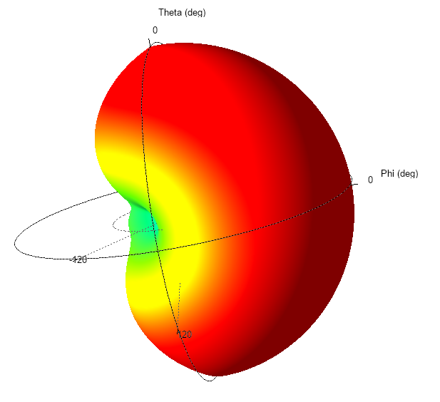
Fig. 1. Patch Antenna 3D Polar Plot, Normalized Gain. Exported from HFSS.
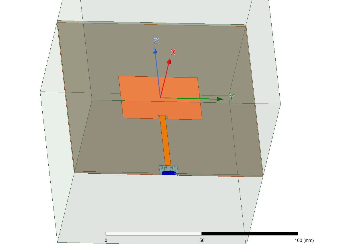
Fig. 2. Patch Antenna Geometry. Exported from HFSS.
Interpolation Output
Next, I used a script to extract the azimuth and elevation cuts as text files from the CSV with the full 3D pattern. I used this file as an input to generate the following 3D graphs with PIE:

Fig. 3. Patch antenna reconstructed 3D pattern, normalized gain, summing algorithm.
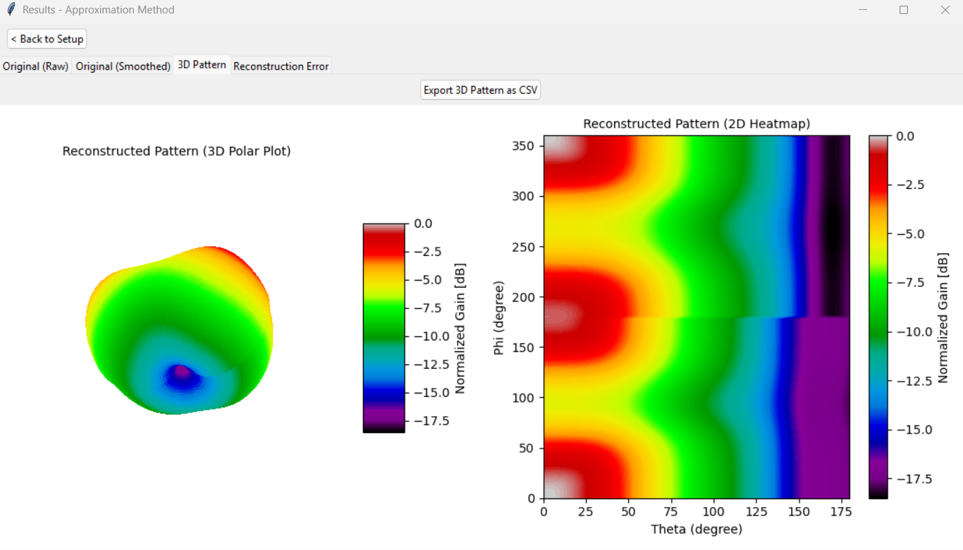
Fig. 4. Patch antenna reconstructed 3D pattern, normalized gain, approximation algorithm.
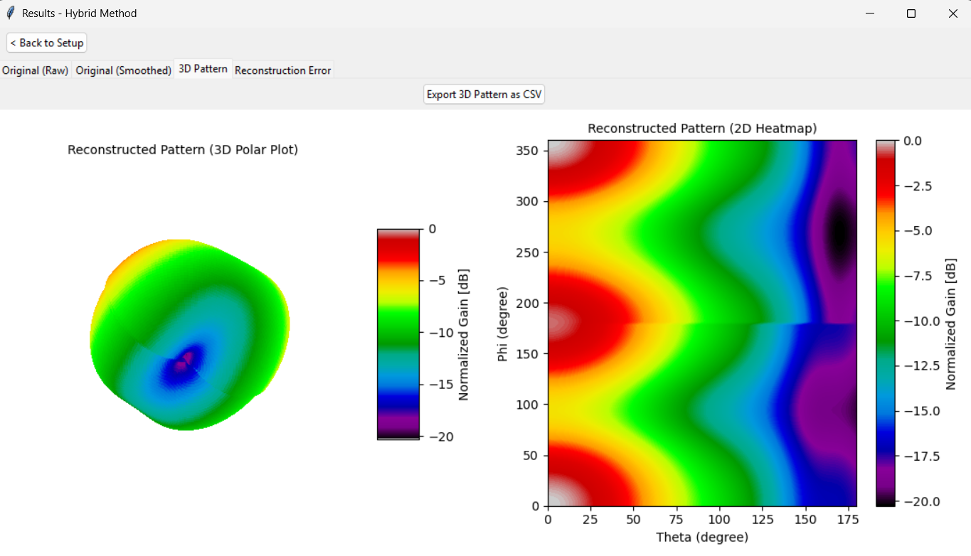
Fig. 5. Patch antenna reconstructed 3D pattern, normalized gain, hybrid algorithm.
Visual Error Analysis
Now that I had the CSVs for both the 3D pattern from HFSS and the 3D pattern from PIE, I used a script to calculate and visualize the error.
Summing Algorithm
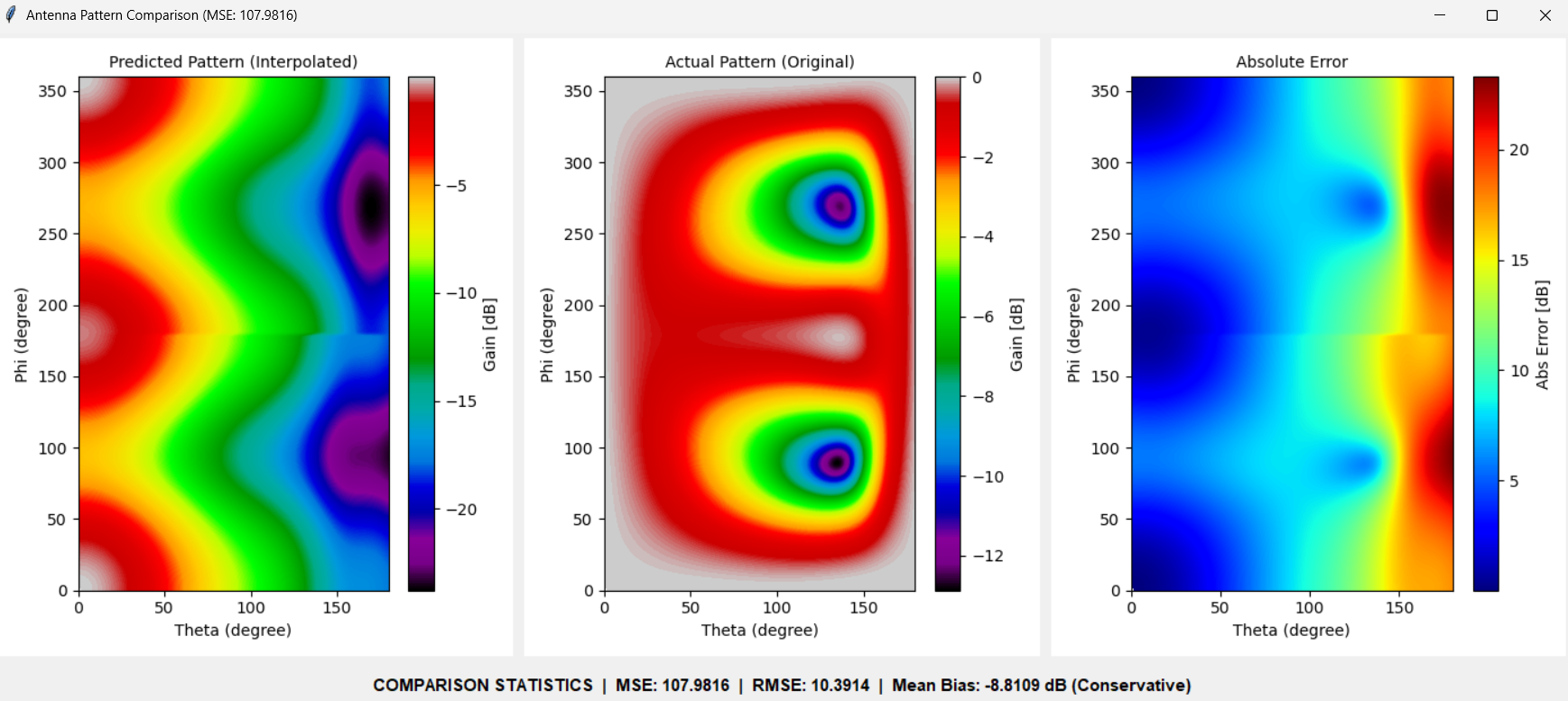
Fig. 6. Patch antenna error plots, summing algorithm.
-
The main lobe has been roughly reconstructed. However, there is a noticeable low-gain band around on the radial axis. This band seems to drive error in the forward hemisphere.
-
The location of the nulls has been correctly captured in the reconstruction with minor angular spreading. There are, however, noticeable errors in gain magnitude as seen in the error.
-
Overall, the mean bias of -6 dB shows that the algorithm has a systematic tendency to underestimate gain considerably.
Approximation Algorithm

Fig. 7. Patch antenna error plots, approximation algorithm.
-
Interestingly, this method was by far the most accurate with the lowest RMSE of 4.8 dB.
-
There is better main lobe reconstruction as the radial null band has decreased.
-
While the gain magnitude of the nulls was correctly reconstructed, even more severe degradation in -axis spread is observed. The nulls are smeared into a continuous band at the aft hemisphere. This causes the most noticeable zone of error in the back lobe (around and on the angular axis).
-
With a mean bias of only -1.33 dB, the Approximation method stayed remarkably close to the overall energy envelope of the actual pattern, though still a slight underestimation.
Hybrid Algorithm
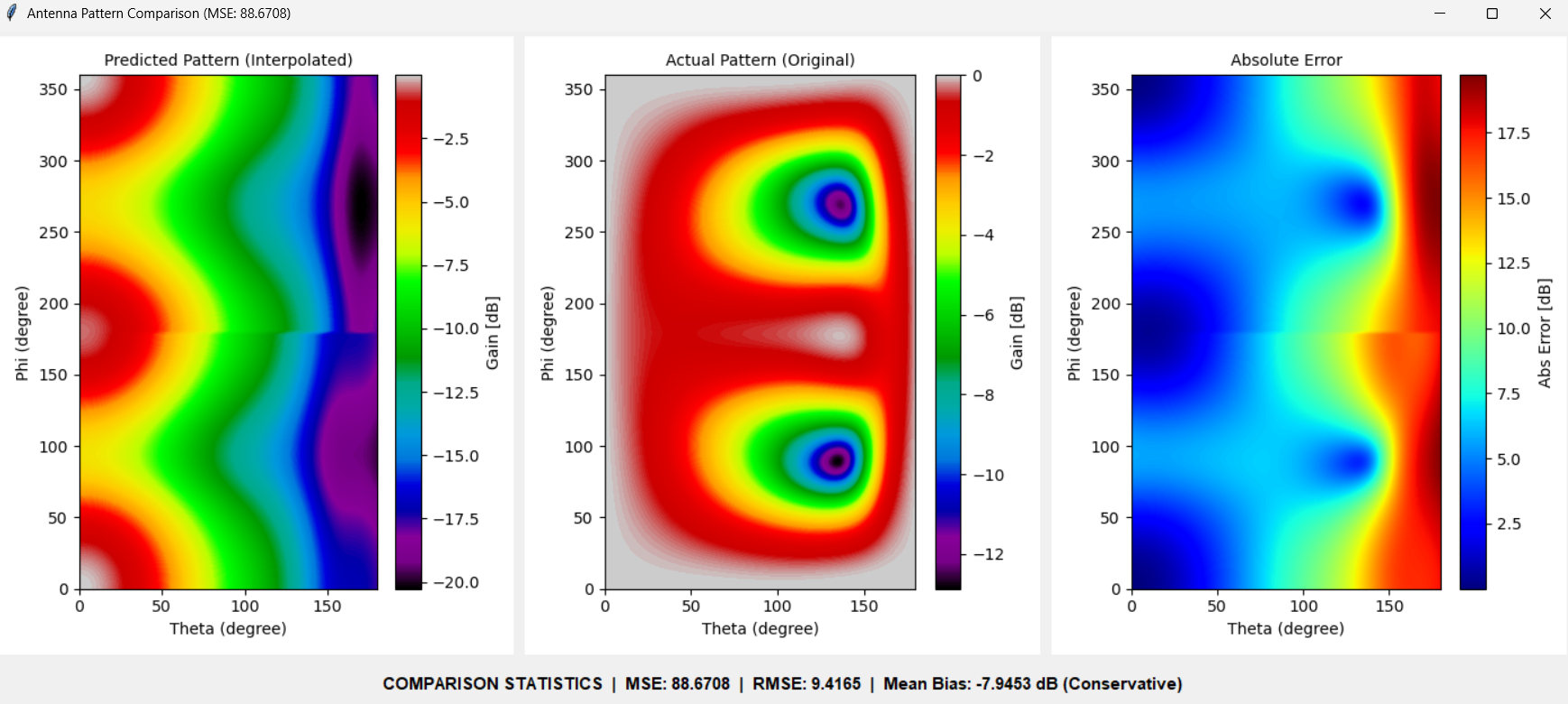
Fig. 8. Patch antenna error plots, hybrid algorithm.
-
Interestingly the hybrid method, which was designed to be the best of both worlds, has the worst performance in this for this pattern. Mixing approximation and summing seems only to have inhereted the errors of both algorithms.
-
Noticeably, the null band in the main lobe has increased in magnitude. Additionally, the aft-nulls have severe angular smearing with the incorrect gain magnitude of summing.
-
The severe mean bias indicates that the Hybrid method aggressively under-predicted the gain.
Comparison of Algorithms
-
In terms of total error, we find that the approximation algorithm achieved the best performance overall (MSE: 22.7562, RMSE: 4.7703), followed by the summing algorithm (MSE: 63.5815, RMSE: 7.9738), then the hybrid algorithm (MSE: 102.0820, RMSE: 10.1036). This is interesting because while it is intuitive to assume that summing would underperform approximation, the tradeoffs between the approximation and hybrid algorithms are much more subtle.
-
From the given patterns, we find that all algorithms exhibit a negative mean bias. This indicates they have a systematic behavior of underestimating the gain.
- However, we find that the approximation algorithm retained the least overall bias (-1.334 dB), followed by the summing (-5.9947 dB), then hybrid algorithms (-8.3444 dB).
- This matches exactly what we expect from the literature: that the approximation algorithm is relatively the most “optimistic”, the summing algorithm is the most “conservative”.